Submerged ARC Furnace Contact Pad and Electrode Kilo Amp Monitoring System
This system that is designed to provide an accurate simultaneous measurement of the individual contact pad kilo Amps and summated electrode current. This has not been possible in the past and H.V. Test (PTY) Ltd. in South Africa have developed a unique system for the measurement of these currents. A number of these systems have been successfully operating on submerged arc closed top furnaces since 1998.
The measurement of the individual electrode contact pad currents (up to Mega Amps/pad) using current transducers, signal processing, isolation and a monitoring system. The system can be integrated into the existing PLC or similar furnace control system.
The goal is to monitor and alarm each contact pad to determine when overloading or under loading occurs due to poor contact or green electrode problems. (Figure 1)
The system can record trends predicting contact pad problems, electrode slipping changes and possible green electrode problems.
Each set of bus tubes is monitored by the system and individual signals are transferred to the control room.These signals can be incorporated into the existing monitoring and recording system or into a dedicated PC / PLC. (Figure 1)
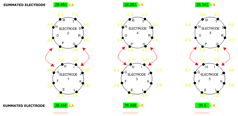
The PC / PLC will present a visual picture of the furnace, the electrodes and the contact pads.
When a contact pad is being overloaded or under loaded the screen will alarm red or green together with an optional audible alarm.
Next to each contact shoe, the current in kA will be reflected together with the phase current per transformer as well as the vectorily summated electrode current.
Figure 1: Typical contact pad distribution
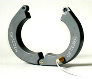
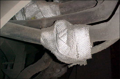
The measuring current transducers (Rogowski Coil) can be designed to suit your bus tube diameter from OD 50 mm up to 500 mm. The coils are a split core and can easily be secured around an existing Bus tube. (Figure 2) The Coils have to be wrapped in fibre glass tape to offer some protection to them – they will withstand an ambient temperature of up to 150° Celsius. (Figure 3)
Figure 2: Split ring Rogowski Coil
Each electrode is serviced by a panel housing the signal conditioning, isolation and passive 4-20mA output signals.
Accuracy: 5% of the full Kilo Amp range. E.g. For 4-20mA which is equivalent to 0-10 kA, the accuracy would be ±0.5kA or ± 0.8mA.
Figure 3: Installed Rogowski Coil wrapped in Thermal Protection
The current measuring transducers are mounted around the bustube as close as possible to the contact pads to be measured. In some cases a ‘çommon’ block or parallel connection is made at the transformer or in close proximity of the flexible connections, with such a design the coils are mounted after this connection to measure individual and not parallel bars. (Figure 4, 5)
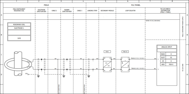
The IP rated conditioning boxes for the signal cards are mounted inside the transformer rooms or within safe distance from the furnace area. The 4-20mA active signals are send to customer PLC, the system can also be adjusted and installed with Remote Terminal Units (RTU’s), I/O Modules and PLC depending on customer specification. (Figure 6, 7)
Figure 4: CPMS Flow Diagram for six in Line Matte
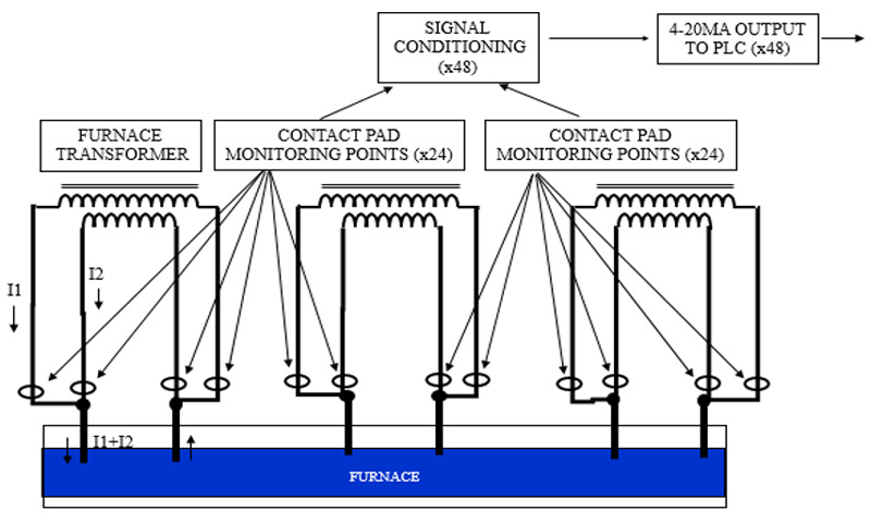
Figure 5: CPMS Flow Diagram for a Delta
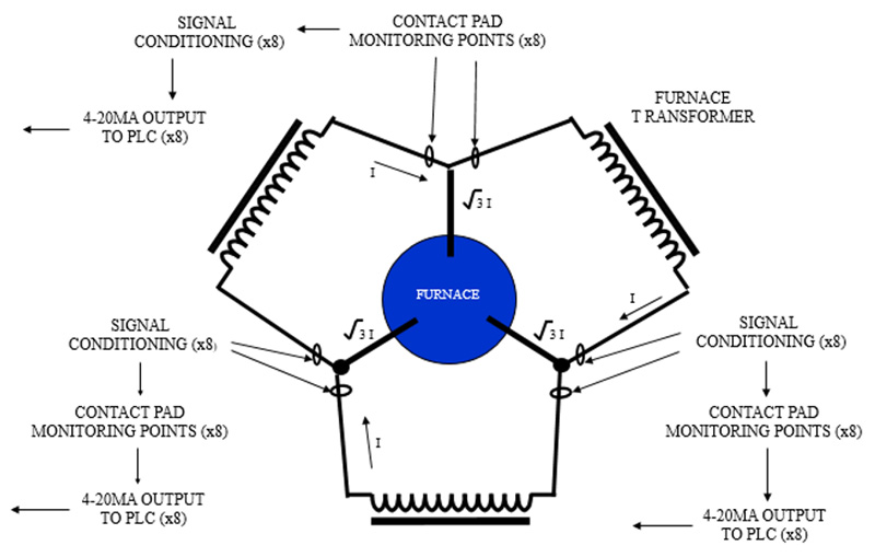
Figure 6: Plan view Drawing of an installed CPMS
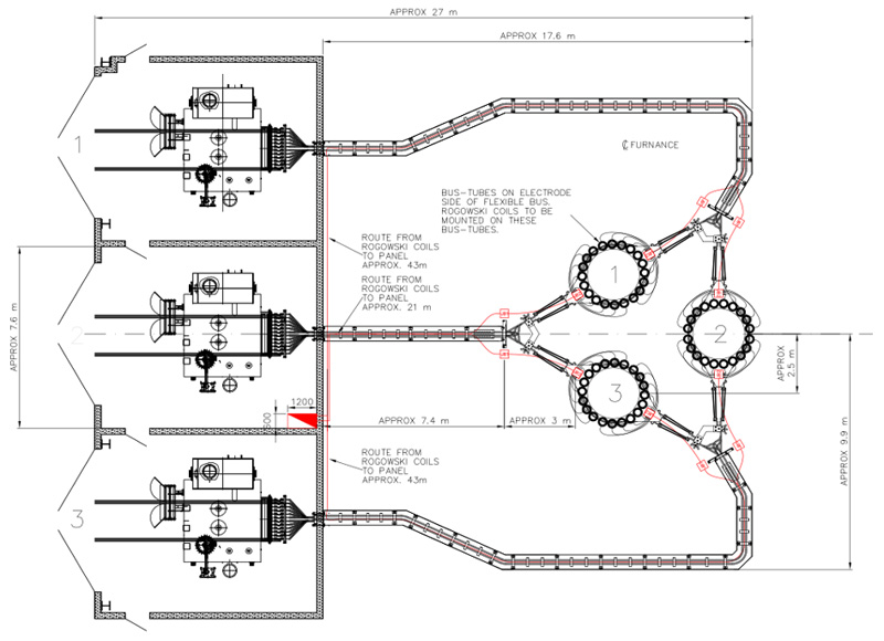
Figure 7: Detail Loop Drawing of an Installed CPMS
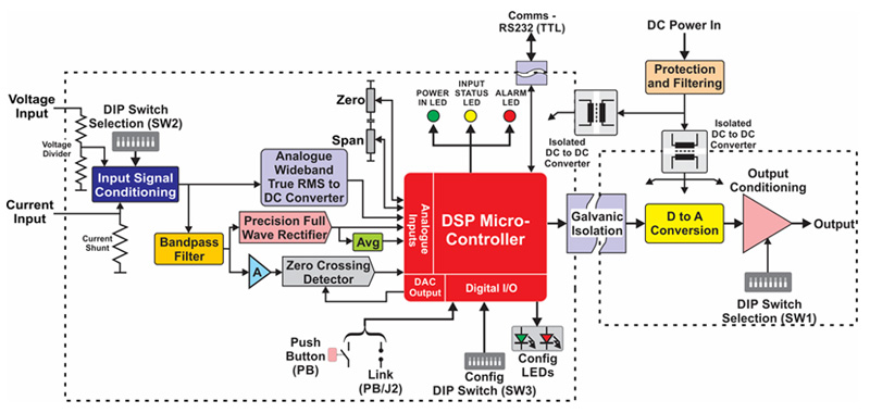
The RMS Wideband Voltage Transmitter is pacifically designed and fabricated for high current and high temperature furnace environments to produce stable and accurate measurement. (Figure 8)The cards accepts a 0 to 430 mV AC RMS Input with range adjustment from zero ±50 mV. Input frequency response up to 1 kHz. With true RMS conversion and response time of less than 1 second. Trimpot zero and span adjustment of the output of ±10%. The Transmitter is designed to eliminate harmonic signals upto 600Hz.
Auxiliary power supply 24 V DC ±5% and Active output 4-20 mA.
Serial/USB cable connection to run and display raw engineering measurement values, easy onsite adjustment of cards can be done so that transmitter output can be matched to that of a calibrator.
Figure 8: SCC Single Line Diagram
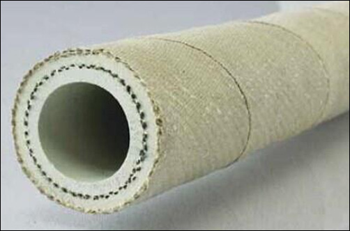
The field wiring from the current measuring transducer to the conditioning boxes are a Teflon twisted pair screened wire that is protected by furnace coolant hose that protects the wiring from the furnace ergonomics such as heat, dust and accidental contact that could damage the wiring.(Figure 9) Single end bonding is applied to eliminate the high current circulation.
Figure 9: Furnace coolant Hose


© 2020 HVT Field Services is a Subsidary of H.V. TEST (PTY) LTD.